-
E-mail
171840725@qq.com
-
Phone
15995361630
-
Address
A503, 159 Chengjiang Middle Road, Jiangyin City
Product Categories
Jiangsu Frisen Fluid Engineering Technology Co., Ltd
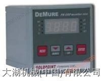
3610 Industrial pH Meter
NegotiableUpdate on 04/21
- Model
- Nature of the Manufacturer
- Producers
- Product Category
- Place of Origin
Overview
3610 Industrial pH Meter 1. Overview: The 3610 intelligent pH meter is suitable for continuous monitoring of the pH value of aqueous solutions in industrial processes in industries such as petrochemicals, refining, metallurgy, machinery, power plants, water plants, papermaking, pharmaceuticals, printing and dyeing, food, and environmental protection. 2. Characteristics and Technical Specifications 2.1 Characteristics (1) High input impedance differential preamplifier amplification, strong anti-interference ability. (2) The input signal can be transmitted over long distances, and the distance between the pH monitor and the pH electrode can reach up to 100 meters. (3) Two way optoelectronic isolated 4-20mA output current, using optoelectronic isolation output technology, anti-interference performance
Product Details
3610 Industrial pH Meter 1. Overview: The 3610 intelligent pH meter is suitable for continuous monitoring of the pH value of aqueous solutions in industrial processes in industries such as petrochemicals, refining, metallurgy, machinery, power plants, water plants, papermaking, pharmaceuticals, printing and dyeing, food, and environmental protection. 2. Characteristics and Technical Specifications 2.1 Characteristics (1) High input impedance differential preamplifier amplification, strong anti-interference ability. (2) The input signal can be transmitted over long distances, and the distance between the pH monitor and the pH electrode can reach up to 100 meters. (3) Two way optoelectronic isolated 4-20mA output current, using optoelectronic isolation output technology, with strong anti-interference ability, can be adapted to various actuators or computer connections. (4) 4-digit LED (or LCD+blue backlight) digital display. (5) Upper, upper, lower, and lower limit alarms, each with rated load 220V/* * relay output. (6) Two channel programmable optoelectronic isolation proportional control pulse output. (7) It can automatically monitor the temperature of the solution. (8) Can the solution temperature be within the range of 0~100 ℃? Perform automatic temperature compensation. (9) Solution high/low temperature alarm, programmable, with rated load 220V/* * relay output. (10) Programmable automatic cleaning?? Device output (relay contact rated load 220V/* *). (11) Self fault detection and alarm. (12) The alarm relay does not move and is programmable. (13) Three point pH correction. (14) Network communication port (RS232 or RS485, optional). 2.2 Technical specifications: (1) Measurement range: 0.00~14.00PH. (2) Accuracy: ± 0.01PH. (3) Reproducibility: ± 0.05% F.S. (4) Linearity: ± 0.05% F.S. (5) Temperature compensation: 0~100 ℃ (manual/automatic). (6) Alarm output: high high/high/low/low low four point relay output, contact rated load 220V/* *, alarm point setting full range programmable. (7) Non action belt: Each point alarm output is non action belt with full range programmable. (8) Current output: Two photoelectric isolated DC 4-20mA outputs, with a load not exceeding 500 Ω and an accuracy of 0.01% F.S. The span is programmable. (9) Pulse output: Two sets of pulse proportional output, 0-99 times/minute, TTL level, programmable span. (10) Cleaning output: Cleaning time 0-180 seconds (programmable); Cleaning cycle: 0 minutes to 48 hours (programmable); Has a rated load of 220V/* * relay output. (11) Environmental temperature: -10~+65 ℃. (12) Relative humidity: ≤ 95%. (13) Supply?? Source: AC110/220V ± 10%, 50/60Hz ± 10%. 3. Install the instrument on the dashboard, clamp both sides with the attached fixing clips, tighten the fixing bolts, and then connect the wires according to the terminal wiring diagram in Figure 4.


