Mainly used for precise control of hydraulic oil direction and flow in industrial automation systems. Here is a detailed introduction:
Model meaning:
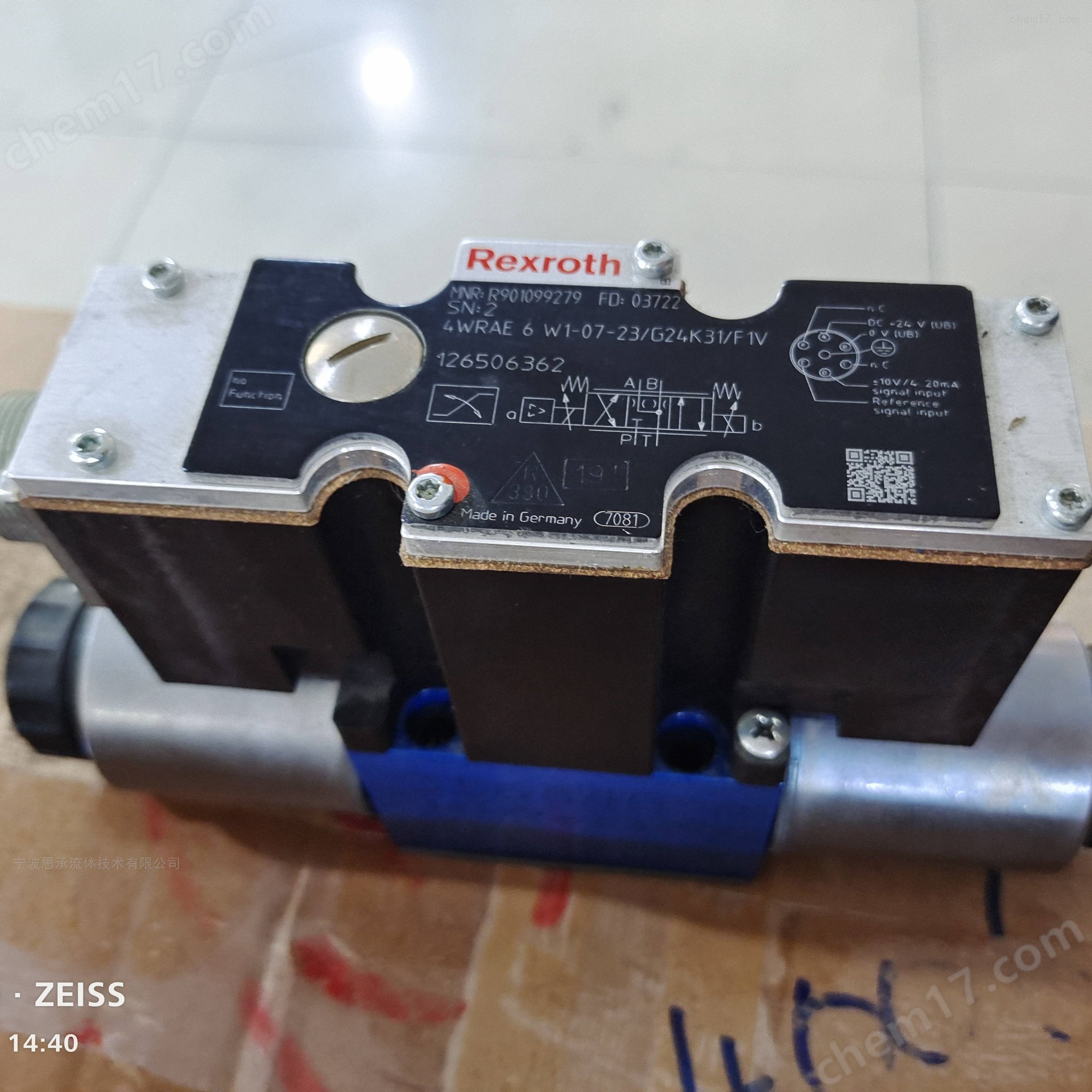
4WREE: Represents a proportional directional valve with electrical position feedback and integrated electronic components (OBE).
6The representative size is 6.
E1: is a symbol, and its specific meaning is related to the functional characteristics of the valve.
08The rated flow rate is 8 liters per minute.
3XComponent series, where 3 represents the series number and X represents the specific version within the series.
VThe sealing material is fluororubber.
24The power supply voltage is 24V.
F1The instruction value ranges from 4 to 20mA.
working principleThe valve is driven by a proportional electromagnet. When the electromagnet is not energized, the centering spring keeps the control valve core in the neutral position; After the proportional electromagnet is energized and activated, it will directly push the control valve core, thereby controlling the direction and flow rate of the liquid flow.
Technical Specifications:
work pressureThe maximum working pressure is 315 bar, with ports P, A, and B all having a maximum working pressure of 315 bar, and port T having a maximum working pressure of 210 bar.
flow parametersThe nominal flow rate is 8 liters per minute, and the maximum flow rate can reach 80 liters per minute.
Other parametersThe ambient temperature range is -20 ℃ to+50 ℃, the storage temperature range is -20 ℃ to+80 ℃, and the weight is approximately 2.4 kilograms.
structural characteristics:
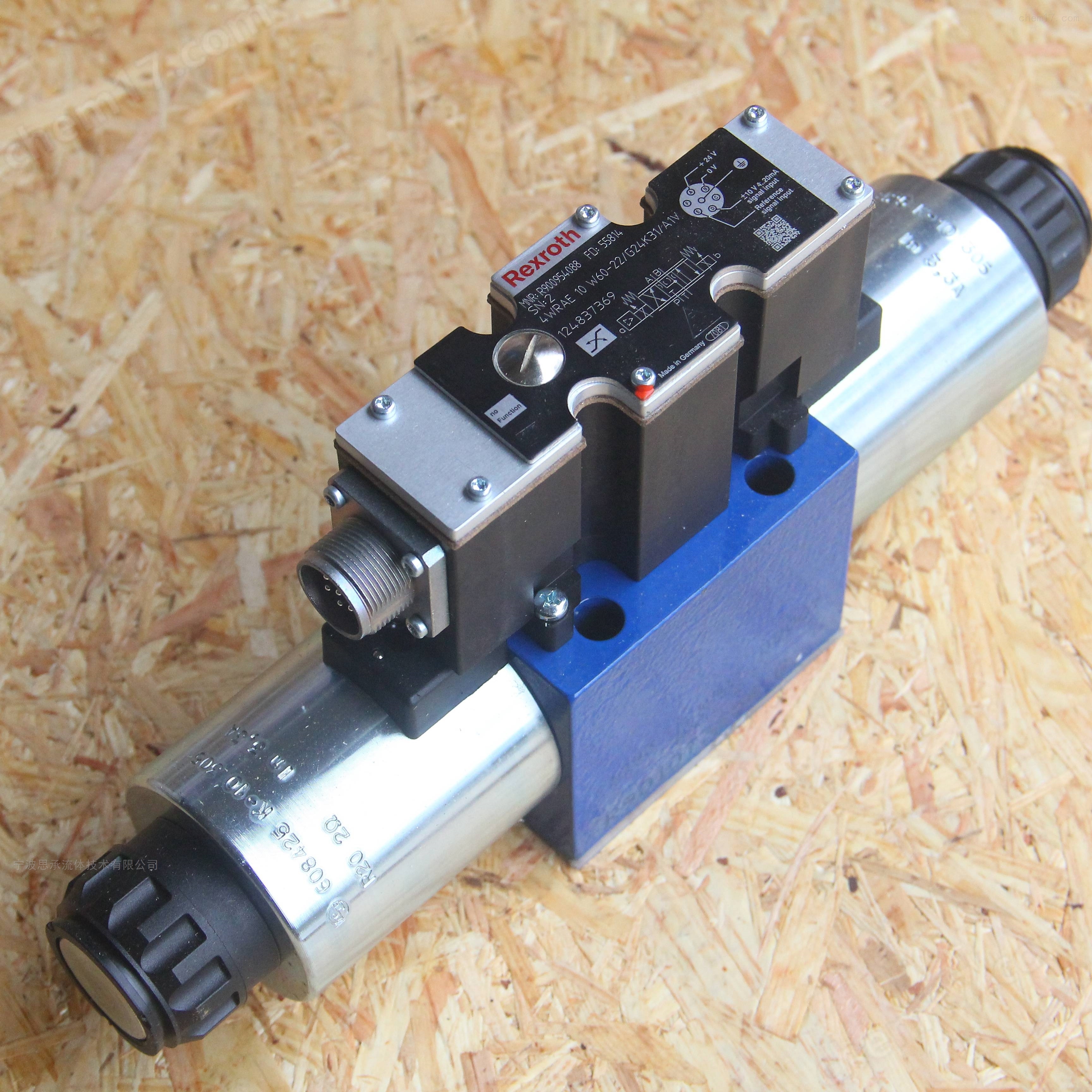
Adopting a panel design that complies with the ISO 4401 installation standard, it is easy to install and connect.
It consists of a housing with connecting surfaces, a control valve core with compression springs and spring plates, and an integrated electronic solenoid valve with central threads.
The solenoid valve is equipped with integrated electronic devices, which can be adjusted by electrical zero point, and the coil can be disassembled separately.
application fieldWidely used in scenarios that require precise flow and direction control, such as machine tools, injection molding machines, metallurgical equipment, etc., such as CNC machine tool spindle feed control, precise adjustment of mold opening and injection speed in plastic machinery, etc.
The correct installation of the Rexroth proportional valve 4WREE6E1-08-3X/V/24F1 requires following standard procedures to ensure its stable performance and service life. The specific steps are as follows:
1、 Preparation before installation
environment check
The installation location should be away from sources of severe vibration (such as motors without shock absorption), high-temperature heat sources (additional heat dissipation is required for temperatures>50 ℃), and corrosive gases, and avoid direct sunlight.
Reserve sufficient maintenance space (at least 15cm around the valve body) for subsequent maintenance and wiring operations.
Component cleaning
Check if there are any residual impurities in the oil port and installation surface of the valve during transportation. Clean hydraulic oil (recommended viscosity 15-30mm ²/s HLP grade oil) can be used for flushing. Ensure that there are no iron filings, welding slag or other contaminants inside the connecting pipeline, and blow the pipeline with compressed air before installation.
Preparation of tools and auxiliary materials
Prepare an installation plate that meets the ISO 4401 standard (matching the installation holes of the valve), with a surface roughness of ≤ 3.2 μ m and a flatness error of ≤ 0.05mm/100mm. Choose high-pressure fittings with metric threads (matching the specifications of the oil port threads), and it is recommended to use fluororubber seals (compatible with the valve's V-shaped seal) for sealing.
Rexroth proportional valve 4WREE6E1-08-3X/V/24F12、 Mechanical installation steps
Fixed valve
Align the installation surface of the valve with the installation plate, ensuring that the positioning pin is accurately inserted into the positioning hole of the installation plate (to avoid force displacement of the valve core).
Use a torque wrench to tighten the installation bolts in sequence (recommended bolt size M6, tightening torque 8-10N · m), using a diagonal uniform tightening method to prevent deformation of the installation surface and leakage
Pipeline connection
Confirm the oil port markings: P (inlet), T (return), A/B (working oil), and connect them according to the system schematic to avoid reverse connection (which may cause the valve core to get stuck). When connecting hoses or hard pipes, avoid radial force on the valve body caused by the pipeline (allowable deviation ≤ 0.5mm/m). The pipeline can be fixed with pipe clamps to eliminate stress.
After the initial connection, manually rotate the pipeline to check for any abnormal stress and ensure that the valve body is not significantly tilted
3、 Electrical Connection Specification
Pre wiring inspection
Confirm that the power supply voltage is DC 24V (fluctuation range ± 10%), matching the "24" parameter of the valve, to avoid connecting the wrong high-voltage power supply and burning electronic components. Check that the control signal type is 4-20mA (corresponding to model "F1"), and prepare a shielded cable (cross-sectional area ≥ 0.5mm ²) with a recommended length of no more than 50m.
Wiring operation
Open the electrical interface cover of the valve and connect according to the wiring diagram: power supply positive (+24V), power supply negative (0V), signal input (4-20mA), shielding layer single ended grounding (connected to the control cabinet grounding terminal).
Tighten the terminal block with a torque of 0.5-0.6N · m to avoid damaging the terminal due to over tightening or causing poor contact due to over loosening. After completion, organize the cables and secure them with zip ties to prevent them from shaking and damaging the insulation layer.
4、 Commissioning and inspection after installation
Check before initial startup
Manually operate the valve core (in power-off state) and confirm that there is no jamming phenomenon.
Check the oil level and filter status of the fuel tank (it is recommended to install a 10 μ m fine filter), and eliminate the air in the system (which can be released by loosening the return pipe).
No load trial operation
Set the system pressure to the lowest+(regulated by the overflow valve), turn on the power, input a 50% signal (12mA), observe whether the valve operates smoothly, and whether there are any abnormal noises or leaks.
Gradually increase the pressure to the working pressure (≤ 315 bar), check the sealing condition of each interface, and if leakage is found, immediately stop the machine for treatment (do not tighten bolts under pressure).
Functional Verification0% (4mA), 50% (12mA), and 100% (20mA) signals correspond to the center position of the valve core, the oil flow status of port A, and the oil flow status of port B. Use a flow meter to detect whether the flow rate matches the set value (nominal flow rate 8L/min).
5、 Precautions
Do not plug or unplug electrical connectors when the valve is powered on to prevent instantaneous high voltage damage to integrated electronic components.
There is no strict restriction on the installation direction (it can be installed horizontally or vertically), but it is necessary to ensure that the movement direction of the valve core is not affected by gravity (such as when installed vertically, the self weight of the valve core may cause zero point deviation, which needs to be recalibrated).
If the system frequently starts and stops, it is recommended to install a one-way valve protection at the P port to prevent pressure shock from damaging the components inside the valve.
Following the above steps can effectively reduce malfunctions caused by improper installation and ensure stable operation of proportional valves in high-precision control scenarios such as machine feed and injection molding machine speed regulation.