-
E-mail
2355335621@qq.com
-
Phone
18030129913
-
Address
Room 602, No. 482 Xinglinwan Road, Jimei District, Xiamen City
Xiamen Yingyi Automation Technology Co., Ltd
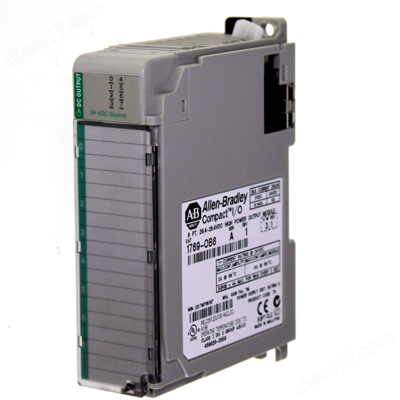
Sharing the correct installation steps for the 1734-OB8 I/O digital DC source output module
Date: 2025-08-13Read: 41
In modern electronic devices and automation systems, the 1734-OB8I/O digital DC source output module serves as a key component for providing stable and accurate DC power, and its correct installation is crucial to ensuring system performance. Whether in laboratory testing or industrial applications, following the correct installation steps can not only ensure the normal operation of equipment, but also extend its service life and improve safety. This article will provide a detailed introduction to the correct installation steps and precautions for the 1734-OB8I/O digital DC source output module.
1、 Physical installation
1. Installation bracket fixation
Reasonably plan the installation location based on the actual size of the cabinet or mounting board. Use the provided mounting bracket or screws to securely fix it in the designated position, ensuring it is level and stable. Avoid overtightening screws to prevent damage to the module casing or deformation.
2. Connect the power cord
Carefully peel off the insulation layer at the end of the power cord using wire stripping pliers, exposing an appropriate length of conductor (usually 5-10mm). Connect the power cord to the input terminal of the module, paying attention to distinguishing the positive and negative poles and ensuring a secure connection. It is recommended to use a torque wrench to tighten according to the manufacturer's recommended torque values to ensure good electrical contact. For high voltage or high current application scenarios, it is necessary to use appropriate cable cross-sections to avoid overloading and heating.
2、 Electrical connection
1. Signal line connection
According to the system design requirements, correctly connect the control signal lines (such as analog input/output, digital I/O, etc.) to the corresponding terminals. Use color coding or labeling to identify each circuit for easy maintenance and troubleshooting. For sensitive signal lines, their length should be shortened as much as possible and shielding measures should be taken to reduce the impact of external electromagnetic interference.
2. Grounding treatment
Correctly connecting the grounding wire is an important step to ensure safety and suppress noise. Connect the grounding terminal of the module reliably to the system's grounding grid to form a low impedance circuit. Regularly check the grounding resistance value to ensure it is within the specified range (generally not exceeding 4 Ω) to ensure personal and equipment safety.
3、 Debugging and Verification
1. Preliminary power on test
After completing all physical and electrical connections, conduct a preliminary power on test first. Turn off all loads, slowly increase the input voltage to the rated value, and observe the status of the module indicator lights and any abnormal sounds. If any abnormal phenomena are found (such as smoking, odor, flashing indicator lights, etc.), immediately cut off the power, investigate the cause and eliminate the fault before continuing the operation.
2. Functional verification
Use a multimeter or other testing instrument to measure whether the output voltage and current meet the expected values. Adjust the adjustment knob on the module or set the required parameters through the software interface to verify whether its functions such as voltage regulation and current limiting are normal. Record various test data as a reference for future reference.