-
E-mail
he.zhenzhen@yoseenir.com
-
Phone
18771127656
-
Address
Building 19, MCC Continuous Casting Industrial Park, No. 51 Guanggu Avenue
Download
Wuhan Gewu Youxin Technology Co., Ltd
Thermal imaging scheme for railway pantograph monitoring
Date: 2025-07-16Read: 1
Railway pantograph monitoringThermal imaging scheme
During train operation, the pantograph slide plate rubs against the overhead contact system and generates high current, resulting in heat generation and temperature rise of the slide plate. Under normal circumstances, the temperature rise is limited, but if the temperature exceeds the limit, it indicates that there may be a malfunction in the pantograph or overhead contact system. The risk of manually climbing to the top to detect the temperature of skateboards is enormous, especially when the train speed exceeds 100km/h and the contact network voltage is as high as 25kV, which is not realistic. Although the traditional point temperature measurement method avoids the risk of reaching the summit, it is difficult to move the temperature measurement point and can only obtain the temperature of a single point; Even if movement is achieved, the roof environment is complex, and a slight mistake in temperature measurement points may touch the contact network, damage equipment, and even cause circuit faults. The use of infrared thermography for monitoring overcomes these problems: its non-contact temperature measurement does not require climbing to the top; Not affected by rain, snow, and heavy fog; Can obtain temperature information of objects within the entire field of view of the lens, rather than a single point; High temperature measurement accuracy (± 2 ℃ or 2%); The device is compact, low consumption, and does not affect the operation of other components.Gewu YouxinThermal imaging scheme for railway pantograph monitoringProvided more efficient, intelligent and safe protection for train pantograph monitoring.
The pantograph is mainly composed of a chassis, a damper, a pantograph lifting device, a lower arm, a pantograph assembly, a lower guide rod, an upper arm, an upper guide rod, a pantograph head, a sliding plate, and a pantograph lifting air source control valve plate. The lifting device is installed on the chassis and acts on the lower arm through a steel wire rope. There is an air chamber and compressed air in the skateboard. If the skateboard wears out to the limit or breaks, the automatic pantograph lowering device will take effect, and the pantograph will quickly and automatically lower. The transmission lines on the overhead contact line are erected in a zigzag shape with the railway tracks to avoid continuous friction between the pantograph and the high-voltage line, which may cause excessive temperature or uneven wear at a single point. Rotating friction can allow the frictionless part of the pantograph to dissipate heat, resulting in more uniform wear and longer service life. Once a fault occurs on the pantograph, it will cause continuous friction and electrification at a certain point or area, and the temperature will rise beyond the warning value, resulting in the failure of some components or contact network circuits of the pantograph.

Analysis of Monitoring Requirements for Railway Pantographs
1. System requirements:
The monitoring system needs to accurately cover the pantograph slide.
u During train operation, the temperature of the skateboard can be continuously and accurately observed.
u Realize all-weather, real-time, non-contact, and precise temperature measurement.
u Can quickly obtain monitoring data of points of interest.
u Equipped with an infrared thermal imager and a complete set of components.
u All components of the system must meet the relevant parameter requirements.
2. Data requirements:
u Can view and store temperature video data in real-time.
u The data format must meet the parameter requirements.
3. Monitoring scope:
The infrared thermal imaging system requires the staff to dynamically monitor the temperature of the pantograph slide area (3.2m in length, 1.5m in width, and 2m in height) in real time on a monitor.
4. Alarm requirements:
u When the temperature exceeds the set temperature, the system needs to alarm immediately.
u An image of the overheated area needs to be stored.
u Ensure that staff can promptly identify and address potential hazards.
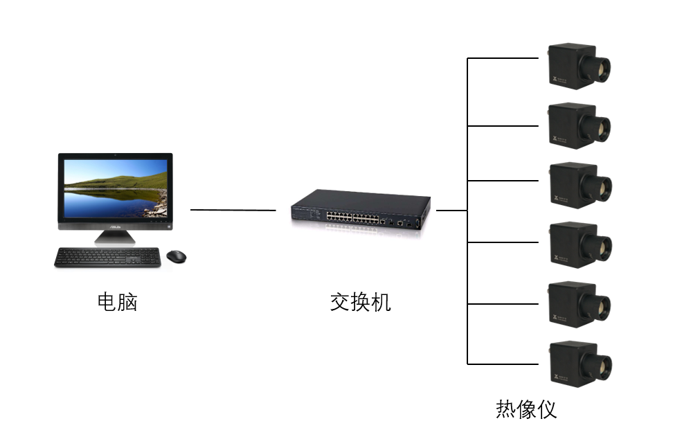
Based on the position and working characteristics of the pantograph slider, the system is designed to set up a monitoring point in front of the pantograph on the roof, which is connected to the vehicle through a network cableInternal host connection. The host can perform real-time monitoring, image acquisition, and temperature data analysis on designated areas, search for the highest temperature point in real time, and trigger an over temperature alarm. It also supports viewing infrared images and video materials from various monitoring points; The monitoring center can automatically or manually switch between displaying images of each monitoring point. The system consists of two parts: the monitoring front-end (monitoring points) and the monitoring center (host). Infrared thermal imagers are installed at the height control positions of several monitoring points as the monitoring front-end; The monitoring center consists of workstations and other equipment, mainly responsible for early warning, display, control, video recording, as well as video digitization and networking functions. The system adopts TCP/IP protocol and has a modular structure, which can flexibly add or remove monitoring points and has good scalability.
Function of Gewu Youxin Railway Pantograph Monitoring Thermal Imaging System
1. Real time monitoring:
Obtain infrared images of the coverage area through the roof monitoring point.
Realize 24/7 uninterrupted monitoring.
The monitoring center can observe the infrared image of the entire pantograph.
Support full video recording.
2. Dynamic monitoring:
Quickly transmit the system through Ethernet cables.
Real time and synchronized transmission of infrared images and other information to the monitoring center.
Realize real-time observation of the dynamic situation of the pantograph.
3. Obtain the temperature of the skateboard contact area:
The operators of the monitoring center can use the thermal imaging software.
Artificially selecting specific areas of the skateboard to obtain accurate temperature.
Assist in diagnosing faults.
4. Data storage and offline analysis:
The system can store temperature image data (screenshots, video streams, temperature streams) returned by the front-end.
Support saving data for the time period of interest.
Offline analysis can be performed using system software.
5. Automatic over temperature alarm:
Real time automatic measurement of the highest temperature of objects within the field of view.
Automatic alarm when the temperature exceeds the preset alarm value.
Output alarm signal.
The monitoring computer emits an alarm sound and can be equipped with an external sound and light alarm device.