-
E-mail
dyh@slectachina.com
-
Phone
15222029577
-
Address
2-1-301 Yunshui Garden, Tanjiang Road, Youyi South Road, Hexi District, Tianjin City
Tianjin Sailaite Technology Development Co., Ltd
Pre installation preparation and material acceptance for special gas pipeline engineering
Date: 2025-10-29Read: 1
As the core facility for transporting high-risk media, the installation quality of special gas pipeline systems directly affects personnel safety, production stability, and environmental protection.
The following are the key operating specifications for the entire process of special gas pipeline engineering installation from design to acceptance:
1、 Preliminary preparation and material acceptance
1. Technical briefing and drawing review
Organize design units, construction units, and owners to conduct technical briefings, clarifying pipeline routing, pressure levels, material requirements, and special process nodes. Focus on checking whether the curvature radius of the elbow meets the requirements of fluid dynamics, to avoid wear caused by sharp turns or vibration caused by turbulence.
2. Material entry inspection
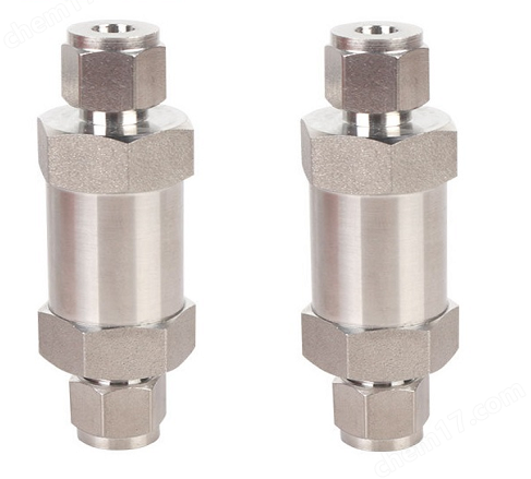
Check the factory certificate, material certificate, and third-party inspection report of the pipe to ensure consistency with the design specifications. Stainless steel pipes need to be inspected for internal and external surface smoothness to prevent defects such as scratches and dents; Double card sleeve joints should undergo air tightness testing and be marked with available status. For specialized pipelines for corrosive gases, additional verification of the effect of inner wall passivation treatment is required.
3. Calibration of tools and equipment
Prepare specialized automatic welding machines, argon arc welding equipment, and gas protection devices, and complete welding parameter debugging in advance. All measuring instruments (such as thickness gauges and level gauges) must be certified by legal institutions and used within their validity period.
2、 Key points for construction control of special gas pipeline engineering installation site
(1) Bracket fabrication and installation
Prefabricated fixed brackets made of channel steel or angle steel are used, and the cutting section needs to be deburred and treated with anti-corrosion measures. The clearance between the sliding bracket rollers should be controlled within the allowable range of thermal expansion displacement to ensure free expansion and contraction during temperature changes.
Anti sway fixing points shall be set at each level of the vertical riser, and anchoring points shall be set at both ends of the horizontal main pipe. The spacing between brackets shall strictly follow the stress calculation sheet, with a maximum limit not exceeding the specified limit, to prevent sagging deformation due to self weight.
(2) Prefabrication and processing of pipelines
Material cutting
Use mechanical cold saws or plasma cutting machines, and prohibit flame cutting to prevent material denaturation. The cut end face should be flat and free of burrs, and rust inhibitor should be applied immediately after the oxide layer is completely removed.
Preparation of groove
According to the welding process evaluation report, the groove form is determined, generally using a V-shaped groove angle of 60 °± 5 °, with a blunt edge thickness not exceeding 2mm. The gap between the joints is strictly controlled within the tolerance range specified in the process card.
Prefabricated assembly
Perform segmented pre assembly on a dedicated platform, with a focus on checking flange parallelism and bolt hole alignment. The prefabricated pipe sections are labeled with the medium name, flow arrow, and weld number for easy on-site assembly.
(3) Welding operation management
Preheating and dehumidification before welding
When the environmental humidity exceeds 80%, the base material should be locally dried. Windproof measures should be taken in the stainless steel welding area, and welding should be suspended when the wind speed exceeds the specified value.
Multi layer and multi pass welding
The root weld bead is coated with TIG to ensure penetration, and the interlayer temperature of the filling layer is controlled to be ≤ 150 ℃. After cleaning each layer of welding slag, the cover welding can continue, and the excess height of the cover weld should be controlled within the range of 0-2mm.
Online quality monitoring
Equipped with X-ray flaw detectors for real-time monitoring of weld quality, with 100% non-destructive testing conducted on critical areas. Welding records include welder numbers, parameter settings, image data, etc., forming traceable files.
3、 Special treatment of key nodes in the installation of special gas pipeline engineering
1. Valve chamber layout
The emergency shut-off valve group should be equipped with an independent concrete valve well, and a collection pit and drainage pump linkage should be set up inside the well. Extend the manual control lever above the ground and mark it clearly to ensure quick opening and closing in case of an accident.
2. Cross grounding system
The metal pipeline is continuously connected throughout the entire process, and the measured grounding resistance is not greater than 4 Ω. The flange connection is overlapped with copper core braided tape, and the contact surface is stripped of paint and coated with conductive paste to enhance conductivity.
3. Integration of leakage monitoring device
Install fixed combustible gas detectors at the low points of the main pipeline and at the ends of the branch pipes, and coordinate the exhaust system to achieve emergency response. The sampling port of the detection probe should face the direction of airflow, and the installation height should be no less than 30cm from the ceiling.