-
E-mail
1415268707@qq.com
-
Phone
13764885152
-
Address
Room 4597, Building 6, No. 1150 Lanfeng Road, Fengxian District, Shanghai
Download
Shanghai Jintong Instrument Co., Ltd
Anatomy diagram of Olympus fluorescence microscope
Date: 2020-04-08Read: 0
Anatomy diagram of Olympus fluorescence microscope
2018/7/26 7:52:45 Publisher: admin
Compared to other methods based on macro sample featuresoptical microscopeCompared to modes such as phase gradient, light absorption, and birefringence, fluorescence microscopy can image the distribution of individual molecular species based solely on the characteristics of fluorescence emission. Therefore, using a fluorescence microscope, it is possible to monitor the precise location of intracellular components labeled with specific fluorescent groups, as well as their associated diffusion coefficients, transport characteristics, and interactions with othersbiologyMolecular interactions. In addition, the significant response of fluorescence to local environmental variables enables the study of pH, viscosity, refractive index, ion concentration, membrane potential, and solvent polarity in living cells and tissues.
Early fluorescence microscope configurations used classical bright field or dark field transmission(transmitted light)optical systemFocus the excitation light passing through the filter onto the sample plane. Collect fluorescence emission and a large amount of excitation illumination through the objective lens, and project it into the eyepiece aperture through a second filter to form an intermediate image. Because the intensity of excitation light is usually several orders of magnitude greater than fluorescence emission, the sample views in these early transmission light microscopes typically have very low contrast and are overlaid on a background filled with scattered excitation illumination. Using a high numerical aperture oil immersed dark field condenser to irradiate the sample at a high tilt azimuth angle helps to eliminate most of the background noise, but it does not provide sufficient illumination except for low numerical aperture objectives. The generated image has poor resolution and very low brightness.
Fluorescence microscope and incident light(reflected lightOr falling light) illumination was initially developed in the late 1920s for observing fluorescence emission in opaque metallurgical samples. Like their bright field counterparts, these reflected fluorescent instruments use a semi reflective beam splitter with a total efficiency of approximately 25% (losing 50% of the illumination after each pass through the mirror). However, the reflected light fluorescence microscope enjoys the advantage of having a high numerical aperture objective as a condenser, and can produce significantly higher levels of images than the transmitted light microscope operated at similar numerical apertures. In addition, the stray excitation light reflected back to the objective lens (at high numerical apertures) is reduced to only a few percent. The dual role of the objective lens in the reflected light microscope also significantly simplifies the alignment task. Focusing only the objective lens on the sample establishes the illumination field and field of view, so that the incident excitation light and observed fluorescence emission follow the same path through the microscope optical series.
When compact mercury vapor and xenon arc discharge lamps were developed in the mid-1930s, technological advancements in lighting sources drove a shift in reflected fluorescence (at least for metallography). During this period, colored glass and gelatin filters also became more complex, enabling the use of halogen lamps to apply fluorescent dyes excited by blue and green visible light. Anti reflective coatings and improved glass formulations led to significant improvements in objective lens design in the 1940s, but the fundamental contribution to the development of incident light fluorescence microscopes was the introduction of a dichroic beam splitter (also known as a dichroic mirror) by Russian optical scientist Eugeniy Brumberg in 1948. This innovation overcomes the inherent light loss problem of using ordinary half mirrors in reflective light microscopes. Reflected light fluorescence microscopy was first widely commercialized by Johan S. Ploem in the late 1960s, who played an important role in developing the Wild Leitz Ploem Opak, which includes multiple interchangeable optical modules and is equipped with various fluorescence microscope filter combinations.
The basic strategy of falling light fluorescence microscopy
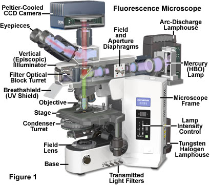
The vast majority of reflected light fluorescence microscopes are currently the preferred methods for wide field studies of incoherent light sources, as well as those conducted using laser scanning confocal and multiphoton instruments. This popular fluorescence microscopy mode is also known as incident fluorescence, reflected fluorescence, or simple epifluorescence. A typical modern reflected light fluorescence microscope is also equipped with various contrast enhancement modes for observing transmitted light, as shown in Figure 1. The microscope includes a three eye observation head coupled to a charge coupled device (CCD) imaging system, with two illumination sources, one for transmitting light and the other for observation (tungsten halogen and mercury arc discharge, respectively). The microscope designed can combine or alternate the phase contrast of reflected fluorescence and transmitted light, differential interference contrast (DIC), polarized light or Huffman modulation contrast observation.
The basic feature of any fluorescence microscope is to provide a mechanism for exciting the sample, which has selectively filtered illumination, and then uses a second filter to separate weaker fluorescence emissions to form images with high sensitivity on a dark background. In many experiments, the concentration of local probes in biological samples is very low, and only a small portion of excitation light is absorbed by fluorescent substances. In addition, the percentage of secondary fluorescence emitted is even lower in those fluorescent groups that can absorb a certain amount of irradiation. The obtained fluorescence emission brightness level will be three to six orders of magnitude lower than the brightness level of the illumination. Therefore, the fundamental problem of fluorescence microscopy is to generate efficient illumination of the sample while capturing weak fluorescence emissions that are effectively separated from stronger illumination bands. In modern fluorescent instruments, these conditions are met by a combination of filters that coordinate excitation and emission requirements based on the action and characteristics of a dichroic beam splitter.
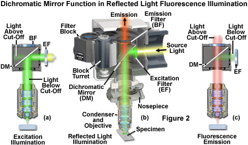
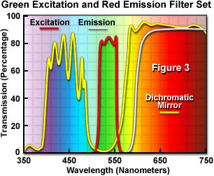
Figure 2 outlines the principle behind the function of a dichroic beam splitter (mirror) in a reflected light fluorescence microscope, which includes a hypothetical sample containing a fluorophore that is excited in the green region (550 nanometers) and emits fluorescence at red wavelengths (620 to 660 nanometers). Visible spectrum. High intensity light sources output a wide range of excitation wavelengths with high flux density (typically covering most of the ultraviolet and entire visible spectrum), which pass through the illumination and first encounter a filter (labeled EF; see Figure 2 (a)) that selects the appropriate excitation band. In this case, the filter efficiently passes light with wavelengths between 510 and 560 nanometers, but also allows other wavelengths to pass through to a smaller extent. The excitation light then reaches the dichroic mirror (DM in Figure 2) and is reflected into the rear aperture of the objective lens to form a conical illumination that illuminates the sample. The dual color mirror is located in the optical path at a 45 degree angle and is designed to selectively reflect wavelengths between 490 and 565 nanometers (as shown in Figure 3), while transmitting shorter and longer wavelengths.
The transmission curve of the filter combination used to separate the excitation light from the fluorescence emission in Figure 2 is shown in Figure 3. The excitation filter spectrum (red curve) shows a high level of transmittance (approximately 80%) between 510 and 560 nanometers. Center wavelength (CWL) is 535 nanometers. The dichroic mirror (yellow curve) reflects the wavelengths in the excitation spectral region, while passing through higher and lower wavelengths with relatively high efficiency. Note that the percentage transmittance on the two-color mirror curve corresponds to 100% reflection. The significant decrease in transmission distribution between 490 and 570 nanometers (which represents the peak reflectivity) is used to reflect the wavelength band entering the sample from the excitation filter at a 90 degree angle. The latter component in the optical series, namely the emission or barrier filter (white curve), transmits wavelengths above 590 nanometers, corresponding to visible light with yellow, orange, and red colors. The boundaries between the transmission and reflection bands of various superimposed spectra are designed to be as steep as possible to ensure that the reflection and transmission wavelengths are almost separated. The pattern of sine rising and falling peaks in the dichroism spectrum is a common effect of thin film deposition process, known as "ringing continuously". The performance of this filter combination is excellent, clearly demonstrating the rapid development of thin film interference filter technology.
Because only narrow bandwidth light is reflected by the dichroic mirror, the wavelength of the excitation filter that is shorter than 490 nanometers and longer than 565 nanometers is also transmitted through the dichroic mirror, as shown by the light above the cutoff. In Figure 2 (a). Note that the reflection of excitation light is not 100% effective, therefore, a small amount of green light passes through the dichroic mirror without being reflected. Additionally, not all light with wavelengths greater than 565 or less than 490 nanometers passes through the mirror. A small portion of this light is reflected by the mirror through the objective lens onto the sample.
The fluorescence emission of the sample excited by green light (mainly at the red wavelength) is focused by the objective lens and passes through a dichroic mirror and a barrier filter (above the cut-off light in Figure 2 (c)). The barrier filter (marked as BF in Figure 2) is specifically designed to only allow light with wavelengths greater than 590 nanometers to reach the microscope eyepiece and/or detector. When used for this task, the barrier filter effectively prevents the excitation light wavelength reflected from the sample (and successfully passing through the dichroic mirror) from reaching the detector. However, most of the excitation wavelengths returned from the sample are reflected by the dichroic mirror (light below the cutoff light in Figure 2 (c)) to the excitation filter and emitter. The net effect of the filter configuration shown in Figures 2 and 3 is to separate excitation light with significantly higher intensity from weaker fluorescence emission. In all cases, as shown in the figure, the cutoff level of the filter involved in the fluorescence microscope is not the same, but it can allow some light outside the wavelength range to penetrate. The entire event sequence is shown graphically in Figure 2 (b), which illustrates the optical path and strategic filter arrangement required for an effective reflected light fluorescence microscope.
Vertical Fluorescent Illuminator
The core of modern fluorescence microscopes is the universal vertical reflector, which is inserted into the observation tube and carries the objective lensobjective lensBetween converters, as shown in Figure 1 and Figure 4. The lighting fixture is designed to guide the light generated by highlights - by first directing the light through the microscope objective towards the direction of the sample, and then capturing the light emitted by the sample using the same objective, placing the intensity source on the sample. This type of lighting strategy has several advantages. The microscope objective first serves as a well calibrated condenser, and then collects imaging fluorescence emissions for transmission to the eyepiece or camera detection system. Therefore, the objective lens is always aligned correctly with respect to each function. In addition, most of the excitation light scattered or reflected by the sample (at a 360 degree angle) is far away from the front lens element of the objective lens, rather than directly projected into the glass, as in the case of transmitted fluorescence irradiation. This effect is called frontal illumination and is particularly suitable for thick specimens. Afterwards, the illuminated specimen area is restricted to the same observed area, and both illumination and light collection can utilize the full numerical aperture of the objective lens.
At the far end of the vertical lighting fixture is a light box (see Figure 4), which contains high-intensity arc discharge or filament based incandescent light sources. The popular lighting source is a high-pressure 100 watt mercury arc lamp (HBO, commonly known as a burner), but xenon and metal halide arc lamps, lasers, and tungsten halide incandescent lamps can also be used for this purpose. The light emitted by the light source is focused by a condenser lens system and travels along the interior of the illumination device parallel to the desktop and perpendicular to the microscope axis. The emitter design shown in Figure 4 includes a multi-component collector lens system, but also implements non spherical lens elements to improve chromatic aberration correction in the near-infrared and ultraviolet regions. A thermal filter designed to remove or suppress infrared wavelengths is placed inside the lightbox itself or adjacent to the lightbox mounting bracket at the rear of the vertical lighting fixture. In addition, some microscopes include systems near the dual frequency or multi frequency excitation balancer lightbox (see Figures 4 and 8) that selectively filter out wavelengths that are not needed for excitation, in order to fine tune the performance of the fluorescence filter group included at the other end of the illumination.
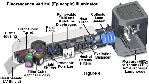
Also located near the lightbox in the vertical lighting fixture is a set of neutral density filters that can be used to adjust the total intensity of light passing through the system and reduce fluorescence fading or photobleaching. These filters are typically installed on slider frames, allowing them to quickly insert and remove from the optical path while observing sample fluorescence. In order to establish K ö hler illumination, the vertical illumination includes a combination of a centered aperture and a field of view aperture, both of which have variable aperture sizes that determine the size of the field and illumination intensity. The alignment of aperture and field stop, as well as the adjustment of aperture size, are achieved through several pairs of knobs located on each outer side of the vertical lighting fixture housing. In some designs, a slider knob is provided to remove the entire aperture component from the light path in order to maximize the amount of light passing through the luminaire. Other microscopes include fixed size pinholes mounted on sliders that can be inserted into the optical path, greatly limiting the illumination field and suitable for special applications such as fluorescence recovery after photobleaching (FRAP) investigations.
In the vertical illumination optical series, the field aperture and aperture are followed by the field lens, which is necessary for diffusing light and generating sufficient illumination field to establish Kohler illumination. Behind the field mirror, all modern vertical luminaires include a shutter (with manual switch control) that prevents strong excitation light from reaching the filter set and sample when fluorescence is not observed or recorded. Shutter is a key feature of fluorescence microscopy, as continuous irradiation of the sample can significantly reduce emissions caused by photobleaching, and high-intensity light is unhealthy for living cells. In addition, the shutter keeps the arc discharge lamp in an active state (reducing preheating time), while using transmitted light to instantly inspect the specimen. Fluorescence microscopes are typically equipped with electronic shutters that allow for quick remote control of illumination. The anti UV shield (marked with the breathing shield in Figure 4) is installed at the front of the lighting fixture housing to protect the operator from accidentally leaking potentially dangerous shortwave ultraviolet radiation when the shutter is open. The shield serves a dual purpose by protecting the specimen from exhaled gas during observation.
Several vertical lighting designs provide slots for rectangular polarizer frames, which can be used for fluorescence polarization research. In most cases, the polarizer is inserted into the illumination path behind the field mirror (away from the conjugate plane), but before the shutter (see Figure 4). Polarizers can be fixed in place with a predetermined transmission orientation or installed on a gear set, allowing the direction of the transmission axis to be changed by using a finger wheel. Due to the polarizer being installed in a sliding frame, it can be easily removed from the optical path when not in use. The accompanying analyzer (the second polarizer required for fluorescence anisotropy measurement) can be installed in a vertical illumination device above the filter block turret or in a specially designed polarizing microscope middle tube. Auxiliary tubes can usually be inserted into gradually changing rotating polarizer units to ensure precise positioning of the analyzer transmission orientation relative to the polarizer and microscope optical axis.
The rear stage of the vertical illumination includes a rotating turntable or sliding bracket, which is equipped with an optical block containing a combination of fluorescent filters. When a specific combination of fluorescent filters is required for imaging, the filter block rotates (or slides) into the optical series. A single block contains a set of matched excitation and emission filters, as well as a dichroic spectrometer, all of which are carefully positioned to maximize sample illumination and capture fluorescence emission at specific wavelengths. The optical block turret and slider bracket can load three to six individual blocks, with one located in the optical path and the other blocks rotating or sliding out in temporary storage. When observing samples labeled with two or more fluorescent probes, these attachments can quickly switch between fluorescent filter groups. Transmission illumination is used in microscopes equipped with fluorescent luminaires to facilitate the use of virtual optical blocks mounted in slots on turntable or slider supports. The virtual block prevents excitation emission (when the shutter is open), but does not contain any filters and allows light to pass through the observation tube unobstructed from the objective lens.
In a standard modular upright microscope, the vertical illumination device is located atmicroscopeBetween the framework and the observation tube (see Figure 1). Many manufacturers offer an intermediate tube that can be inserted between the lighting fixture and eyepiece unit for polarizers, DIC prisms, or other accessories. Modern microscope frameworks are often the result of computer-aided design efforts that result in significant vibration reduction and enhanced ergonomic features. Synthetic materials, such as metal based ceramics and aluminum composites, can significantly improve the static and thermal rigidity of the frame, enabling the instrument to withstand the stringent requirements of advanced fluorescence technologies that require vibration elimination for imaging weak fluorescence emissions over a long period of time.
K ö hler fluorescence microscope illumination
In a fluorescent vertical illumination device, the light source is positioned such that the filament or arc discharge plasma sphere is located near the main focal point of the condenser lens. In K ö hler lighting, the spotlight lens plays a significantly increased role as an auxiliary light source to enhance overall illumination. One of the main requirements of K ö hler illumination is that the image of the filament or arc must be ultimately projected onto the back focal plane of the objective lens, which is also twice the size of the (usually high numerical aperture) condenser during the excitation period of reflected light irradiation. Ideally, the light source should fill the entire aperture of the objective lens to maximize radiation intensity and generate a uniformly illuminated field. In some cases, hotspots. However, since diffusion filters can also reduce illumination, they should be avoided as much as possible.
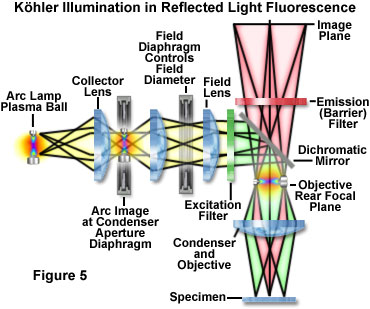
In the reflected light K ö hler illumination (illustrated in Figure 5), the image of the light source is focused by a condenser lens onto an aperture diaphragm located in the vertical illumination device. The aperture size of the illuminated field is determined by the fact that the aperture of the aperture shares a conjugate plane with the rear aperture of the objective lens and the arc or filament of the lamp. The light source, vertical illumination aperture stop, and objective lens back focal plane (pupil) together form a conjugate plane illumination group. Unlike transmission light microscopy, the aperture and light source are imaged onto the aperture plane behind the objective lens (acting as a condenser), rather than physically located at that position. As an additional benefit of this configuration, all obstacles (such as iris apertures) are removed from the optical path when the objective provides excitation illumination or when an image is formed by concentrated fluorescence emission. Opening or closing the aperture stop is used to control stray light and adjust the intensity of illumination (numerical aperture) without changing the size of the illumination field. In images, adjusting the aperture stop can affect brightness and contrast.
The imaging or field group of conjugate planes in reflected light K ö hler illumination consists of a field aperture, a sample surface, and an intermediate image plane. Therefore, when the on-site aperture is focused on the sample plane, the image of the light source is significantly removed from the focus in order to provide a uniform illumination field. The field of view aperture controls the size of the illumination field without affecting the illumination intensity of the observed area. In practice, the aperture size of the field stop should be as small as possible to increase image contrast and reduce the degree of photobleaching in areas that are not directly observed. Although the illumination intensity generated by most arc discharges and filament light sources is uneven, K ö hler illumination can uniformly illuminate the sample field. After correctly configuring the microscope, the back focal plane of the objective lens is illuminated, providing a uniformly bright area from edge to edge. In an ideal scenario, K ö hler illumination bathes the sample with a set of converging wavefronts, each formed by individual points on the light source that are imaged into the aperture of the condenser. In a correctly configured fluorescence microscope, the result is image contrast and resolution. In an ideal scenario, the sample is bathed in a set of converging wavefronts, each generated by a different point on the light source imaged to the aperture of the condenser. In a correctly configured fluorescence microscope, the result is image contrast and resolution. In an ideal scenario, a set of converging wavefronts is used to bathe the sample, with each wavefront being imaged bySpotlight lensGenerated by different points on the aperture of the light source. In a correctly configured fluorescence microscope, the result is image contrast and resolution.
Light source and lighthouse
For strict quantitative analysis in fluorescence microscopy, sample irradiation must be constant in time and space throughout the entire field of view. The instability over time usually reflects fluctuations in lamp radiation caused by changes in power output. On the contrary, the spatial disturbance commonly observed in arc lamps comes from a phenomenon called scintillation, where the plasma sphere moves back and forth on the electrode. Flashing is usually caused by power fluctuations, small changes in electrode resistance, or mechanical vibrations. Filament based light sources, such as popular tungsten halide lamps, are very stable when operating under constant DC power from a regulated power supply. Usually, the light source should be selected based on its spectral content, filament size compared to the aperture region behind the objective lens, spatial and temporal stability, and uniformity of field illumination. Special attention must also be paid to the intensity of the light source, as the narrowband wavelength passed through the excitation filter only includes a very small portion of the total output of the emitter.
The main consideration for selecting a light source for fluorescence microscopy is related to the research being conductedfluorescent dyeThe quantum yield and absorption related UV and visible spectral distributions. In addition, the light source must be compatible with the sensitivity of the detector used to capture the image, whether it is the human eye, traditional film, photomultiplier tube, enhanced video tube, or digital camera system. The choice also depends on the lighting mode. Using arc discharge or tungsten halogen sources to meet the requirements of wide field fluorescence microscopy, while confocal and multiphoton microscopy need to adapt to various laser systems. The use of tungsten and tungsten halogen incandescent lamps has achieved limited success because most of their emissions occur in the red and infrared regions of the spectrum, while most fluorescent groups are excited by ultraviolet, blue, and green wavelengths. In addition, the light output of arc discharge lamps is 10 to 100 times brighter than that of 12 volt quartz halogen lamps typically used for transmitted light irradiation. The popular light source for wide field fluorescence microscopes is mercury arc lamps, which are typically included in the basic model microscope configuration. In some cases, xenon and metal halide arc lamps are used, but these are usually limited to special cases where the spectrum and intensity distribution match the requirements of specific fluorescent groups.
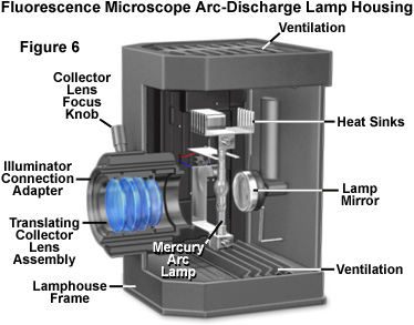
The design of mercury and xenon lamps is similar, except for the physical dimensions and gas inside the bulb casing. The mercury lamp contains two electrodes sealed under high pressure in a quartz glass bulb, which also contains vaporized elemental mercury. When the power is turned on, a series of high-voltage pulses are sent to the electrodes, ionizing a small portion of mercury gas and igniting the lamp. After firing, the voltage decreases and ionized gas is used to carry current and generate a plasma sphere formed between the two electrodes. During the operation of the lamp, the evaporation of mercury generates a large amount of heat and pressure inside the glass bulb, ultimately producing high-intensity light. The light generated by mercury arc lamps is continuous in the ultraviolet and visible spectral ranges, concentrated at discrete wavelengths of 365, 400, 440, 546, and 580 nanometers. From ultraviolet to infrared, xenon lamps have a more uniform intensity distribution throughout the entire spectral range. The selection of fluorescent dyes is crucial for determining the appropriate light source for fluorescence microscopy. Some fluorescent probes have excitation bands that coincide with prominent mercury lines, while others benefit from a more uniform distribution of irradiation from xenon lamps.
The correct alignment of the arc lamp in a fluorescence microscope is crucial for achieving Kohler illumination and avoiding bright and dark areas in fluorescence images. Therefore, the quality of the lightbox can usually be judged by the stability of correct lamp alignment and the efficiency of the adjustment knob used to maintain alignment. The lamp holder should be equipped with a lamp centering screw to center the curved image in the rear hole of the objective lens, and the light box should include an infrared filter to block long wavelengths in far red and infrared, thereby generating a large amount of heat. Some lightbox designs have a built-in red suppression filter (such as Schott BG38) or slots for this filter to eliminate the red background seen through the field of view in certain applications. In addition, the lightbox itself should not leak harmful ultraviolet wavelengths, and preferably, if the housing is accidentally opened during operation, a switch should be included to automatically turn off the light. Afterwards, the lightbox should be sturdy enough to withstand possible burner explosions during operation.
The wide diversity of applications in fluorescence microscopy typically requires a range of light sources to meet the requirements of specific fluorescent groups and imaging conditions. In some cases, combining with ultra sensitive camera systems may require very low radiation, while for other studies, strong laser excitation may be required to kill live cells or selectively bleach fluorescent groups. Wavelength requirements typically span the entire visible region of the spectrum, as well as the ultraviolet and infrared portions. Due to the inability of a single light source to meet these multiple lighting requirements, manufacturers now offer adapters that can simultaneously connect two or more lamps to a single microscope.
Fluorescent filter combination
As mentioned earlier, the light passing through the lens and aperture of the vertical illumination ultimately encounters the excitation filter housed in the optical block, which is positioned to coincide with the axial intersection point between the illumination path and the microscope optical system. The excitation filter selects a narrowband wavelength from the wide spectrum generated by the lamp and transmits them to a dichroic mirror, which reflects the light through the objective lens and illuminates the sample. Before forming an image in a fixed eyepiece aperture, the fluorescence emitted by the objective lens is passed through a dichroic mirror and an emission or barrier filter again. Common filters used for separating bands in wide field fluorescence microscopes include colored glass filters and interference film filters (or a combination of both). Determining the appropriate filter for each step in the illumination and imaging scheme of a fluorescence microscope may cause confusion as it involves a large number of filter manufacturers, each providing a proprietary alphanumeric nomenclature for fluorescence literature.
A typical illustration is shown in Figure 7Fluorescence excitation blockThe anatomical structure, as well as the spectral profiles of dichroism, excitation, and barrier filters. Filter blocks are usually assembled using customized tools provided by manufacturers, so operators can exchange filters and dichroic mirrors. The excitation and barrier filters are fixed in place using clamps, optical glue, or circular threaded mounting seats (see Figure 7). Usually, these filters can be removed without opening the optical block, as they are located above the recessed holes on the flat outer surface. Replacing the two-color mirror is more difficult and requires disassembling the block to enter the interior. Most of the block parts are cast with 45 degree diagonal joints, which can achieve dual tasks by protecting the interior and supporting the two-color mirror at an appropriate angle. After removing the fasteners (pins or small screws) that fix the block parts together, the mirror can be removed by loosening or moving the fixing clip, and then carefully removed from the block. Be careful when handling dichroic mirrors, as interference coatings are often unprotected and prone to scratching. Several filter manufacturers supplying microscope companies also offer various aftermarket filters and dichroic mirrors suitable for various fluorescent applications. After removing the fasteners (pins or small screws) that fix the block parts together, the mirror can be removed by loosening or moving the fixing clip, and then carefully removed from the block. Be careful when handling dichroic mirrors, as interference coatings are often unprotected and prone to scratching. Several filter manufacturers supplying microscope companies also offer various aftermarket filters and dichroic mirrors suitable for various fluorescent applications. After removing the fasteners (pins or small screws) that fix the block parts together, the mirror can be removed by loosening or moving the fixing clip, and then carefully removed from the block. Be careful when handling dichroic mirrors, as interference coatings are often unprotected and prone to scratching. Several filter manufacturers supplying microscope companies also offer various aftermarket filters and dichroic mirrors suitable for various fluorescent applications.
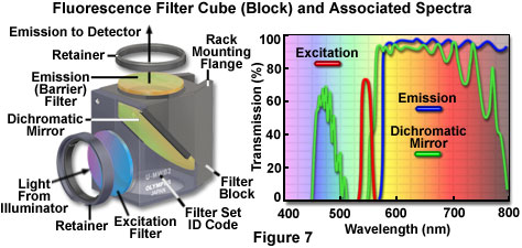
Fluorescent filter design includes long pass, short pass (edge filter), as well as narrowband, mid band, and wideband filter series. The spectrum shown in Figure 7 illustrates examples of several common filter profiles. The emission filter spectrum (blue curve) in Figure 7 is generated by a long pass interference filter with a cutoff wavelength of approximately 575 nanometers. Longer wavelengths are transmitted through filters, while shorter wavelengths are blocked. The narrowband excitation filter from the same group (red curve, Figure 7) has a bandwidth of approximately 20 nanometers, while the dichroic mirror (green curve) has an approximately medium transmission area (455-490 nanometers) and a broadband filter (560) -775 nanometers). Because the dichroic mirror is effectively used as a long pass filter in green, the yellow and red regions of the visible spectrum (560 to 700 nanometers) are processed in the filter group. The working knowledge on how to use the absorption and emission spectral distribution of fluorescent groups to select suitable fluorescent microscope filter sets is essential for the successful implementation of this technology.
A dichroic mirror (or beam splitter) is a key component in the combination of fluorescence microscope filters, similar to a long pass interference type filter, manufactured with tolerances of multiple layers of dielectric materials. The main difference between a dichroic mirror and a standard interference filter is that the mirror is specifically designed for reflection and transmission at a limited boundary wavelength, and must be operated at a 45 degree angle relative to the microscope and emitter optical axis. Position the dichroic mirror so that the interference coating faces the excitation light source, in order to reflect short excitation wavelengths at a 90 degree angle to the sample through the optical system. The same mirror must also act as a transmission filter to transmit long wavelength fluorescence emission from the objective lens to the image plane. Because the wavelength transition region between almost total reflection and large transmission is typically limited to 20 or 30 nanometers, dichroic mirrors can accurately distinguish between excitation and emission wavelengths.
Design a fluorescent filter group to precisely match a specific excitation wavelength band with the reflection area in the dichroic mirror. The result is that the excitation light is effectively reflected onto the sample through the microscope. The fluorescence emission of the sample must match the high transmittance region in the dichroic mirror so that these wavelengths can pass through the detector. Barrier filters are not very important in the entire scheme, but still play an important role in ensuring the elimination of scattering and reflection excitation wavelengths, fluorescence from probes outside the target, and general background intensity caused by spontaneous fluorescence. The important factor in creating a filter bank is to ensure that the transmission, reflection, and emission curves of the filters involved match the emission curves of the corresponding regions. Otherwise, the excitation wavelength may pass through the dichroic mirror and blur the image, or fluorescence emission may unintentionally reflect at the mirror to impair image brightness.
Even in seemingly perfectly matched filter combinations, slight overlap between the spectral distributions of each filter may occur, thereby reducing performance. Of particular concern is the crosstalk between the excitation filter and the dichroic mirror, which allows some excitation light to pass through the mirror and reflect off the walls of the filter block. As mentioned above, light reflected at high tilt angles can partially pass through the barrier filter to reduce image contrast. This type of leakage through the filter is called permeation or crossover, and in fact, all filter combinations occur to varying degrees. One of the main areas of focus for filter manufacturers and microscope companies is improving the design of fluorescent filter combinations to reduce cross levels.

Several configurations of fluorescent filter groups are shown in Figure 8. The filter block turret (Figure 8 (a)) consists of five blocks that can quickly switch between filter combinations while studying at least this number of fluorescent groups. One of the turret slots is usually filled with a virtual optical block or left blank for observation of transmitted light. Fine tune the excitation spectrum using an excitation balancer (Figure 8 (b)) to image samples with dual or multiple labels, including a single interference filter mounted on a rotating joint. The adjustment rod of the rotating excitation balancer moves the bandpass transmission area of the filter to a shorter wavelength. Therefore, when the equalizer filter rotates from a zero degree incident angle (perpendicular to the axis of the vertical illumination) to a large rotation angle of 45 degrees, the bandpass region of the filter can move by a value between 25 and 50 nanometers. The excitation balancer can be used alone or in series to change the excitation bandwidth of the observed fluorescent dye, in order to make the emission intensity equal. This feature enables fine-tuning of the fluorescence intensity in samples containing several probes, such as reducing fluorescence emission from one probe while increasing the intensity of another probe. The excitation balancer can be used alone or in series to change the excitation bandwidth of the observed fluorescent dye, in order to make the emission intensity equal. This feature enables fine-tuning of the fluorescence intensity in samples containing several probes, such as reducing fluorescence emission from one probe while increasing the intensity of another probe. The excitation balancer can be used alone or in series to change the excitation bandwidth of the observed fluorescent dye, in order to make the emission intensity equal. This feature enables fine-tuning of the fluorescence intensity in samples containing several probes, such as reducing fluorescence emission from one probe while increasing the intensity of another probe.
The rapid development of thin film coating technology can be demonstrated by the ability to generate multiple transmission peaks in a single interference filter and to create staggered reflection and transmission bands in a dichroic mirror. When properly matched, two multi band filters and a dichroic mirror can be combined to produce multiple sets of fluorescent filters that can simultaneously excite and observe the emission of several fluorescent groups. The filter group can be obtained from the manufacturer and is suitable for two, three, or even four fluorescent groups in the same sample. The main issues with multiple filter banks are their cost and the excessive crossover or permeation that occurs when the emission from one fluorescent probe passes through the bandpass region used for another. In some samples (and filter groups), penetration has a significant impact on background intensity and image contrast. Many researchers tend to use optimized filter sets to image each fluorophore separately, and then combine the images into a composite.
Advanced fluorescence techniques typically require the use of multiple excitation and emission filters with a single dichroic mirror. For the convenience of these studies, many fluorescence microscopes are equipped with electric filter wheels or sliders, often containing six separate filters (see Figure 8 (c)). Design microscopes for sliders or include special slots for inserting sliders in vertical illumination, or filter sliders can replace sliders that typically contain neutral density filters. In some microscope designs, the vertical emitter can also accommodate the emission slider, or an auxiliary intermediate tube installed between the emitter and the observation tube to accommodate the slider. In upright and inverted microscopes, the electric filter unit containing the excitation filter is typically sandwiched in the vertical illumination optical path between the neutral density filter and the lightbox. Similarly, the electric emission filter unit is placed between the vertical illumination device and the eyepiece observation tube in vertical microscope design, but is typically connected through the same external port as the detector used for inverted instruments. The excitation and emission slider and electric filter wheel are very useful for dual and triple excitation applications using a single dual color mirror. By eliminating the need to reposition filter blocks when observing individual samples, these attachments enable researchers to obtain accurate registration between images.
Objective of fluorescence microscope
In all forms of reflected light microscopy (including fluorescence), image intensity is a function of the numerical aperture and magnification of the objective lens. In fact, the intensity or brightness (defined as the photon flux per unit area and time) increases by the fourth power of the numerical aperture, but only inversely proportional to the square of the magnification:
Intensity α (NA obj) 4/M 2
Among them, NA is the numerical aperture of the objective lens and M. is the magnification factor. It is evident from this relationship that bright fluorescent images will be enhanced bynumerical apertureConcentrate with low magnification (e.g. 0.75/20x) objective lenses. For example, a 60x plan achromatic oil immersion objective with a numerical aperture of 1.4 theoretically produces brighter images than a 100x objective with the same numerical aperture, but a compromise needs to be considered. Increasing the number of internal lens elements (similar to high numerical aperture objectives) will result in an increase in spontaneous fluorescence and a corresponding decrease in intensity reflection from the surface of the internal lens. Usually, manufacturers make a compromise between high positive factor and increased light transmission in their recommended fluorescence microscope lenses.
Generally speaking, high numerical aperture oil (1.3 to 1.4) and water (1.2) immersed in planned fluorite and planar apochromatic lenses produce bright fluorescent images due to their enormous focusing ability. These objective lenses exhibit excellent color correction, enabling them to focus multiple fluorescence emission wavelengths in the same plane. The transmittance characteristics of apochromatic and fluorite objectives are * at a low of about 350 nanometers, which is a requirement for examining fluorescent dyes excited in the ultraviolet region (such as DAPI, Hoechst, Alexa Fluor-350, and AMC). Although there are many internal lenses, these objectives are made of low fluorescence glass with anti reflective coatings to minimize background fluorescence and produce very high contrast images.
Objective lenses designed specifically for special applications are widely used in fluorescence microscopes. This category includes high numerical aperture water immersion, multiple immersion (in oil, water, and glycerol), and ultraviolet objectives with quartz lens elements. For live cell imaging applications, a long working distance objective lens with a calibration ring is required to observe samples through thick (0.5-2 mm) culture bottle walls. By using objective lenses with a very long focal length (working distance) to facilitate deep inspection of thick samples, these lenses can be obtained from several manufacturers for imaging through air or water covered glasses. Designed for long-distance water immersion objectives without cover slips, it also features a Teflon front cone, allowing the objective to be immersed in an aqueous solution. A similar objective is produced for UV excitation (340 nanometers) in water at a working distance of 20 to 30 millimeters (including approximately 5 millimeters of water). For studies with relatively low magnification, it is recommended to use a 20x water immersion objective with a numerical aperture of 0.75 to 0.95. Although very expensive, these objectives produce extremely bright images with negligible fluorophore concentration and/or quantum yield.
Fluorescence microscope accessories
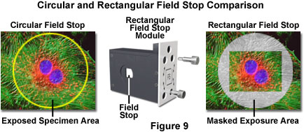
Manufacturers continuously produce useful additional accessory units for their instruments to increase the available choices for the growing imaging applications in fluorescence microscopes. For example, on some microscopes, a rectangular field stop can be selected (see Figure 9), which can restrict the illuminated sample area to improve contrast and reduce photobleaching. Modular on-site aperture replaces traditional aperture apertures (also detachable modules) in vertical luminaires, designed to match the aspect ratio of digital imaging sensors. The rectangular field stop improves the efficiency of Kohler illumination and reduces the signal-to-noise ratio of electronic sensors. As an additional benefit, when using programmable scanning stages in deconvolution research, the image rectangle size can be adjusted to be consistent with the stage step size. Pinholes are similar to rectangular field apertures and can be used for applications that require highly restricted illumination fields.
Other accessories include a dual lamp housing adapter that allows two light sources (such as mercury and xenon arc discharge lamps) to be connected simultaneously to a vertical lighting fixture. Illuminators suitable for exciting lasers can also be used for applications such as total internal reflection fluorescence (TIRF), fluorescence lifetime imaging microscopy (FLIM), ratio imaging, and photobleaching recovery experiments. In addition, most research grade fluorescence microscopes provided by major manufacturers are easily adaptable to their respective laser scanning confocal accessories. The upright microscope receives confocal scanning units through a three eye observation tube, while the inverted instrument can connect the beam scanner to the side or rear port of the microscope frame. The dual port inserted between the vertical lighting fixture and the observation tube can be used to introduce additional light sources or guide fluorescence to more than one detector. Most of these devices come with optional C-mount adapters or standard microscope port accessories.
The design of fluorescence microscopes for electrophysiological research has become very complex. Many are equipped with specialized shock absorbers that can accept various micro manipulator accessories for experiments using fluorescence, infrared differential interference contrast (IR-DIC), and traditional bright field contrast enhancement imaging techniques. The rotating disc of the animal mirror can achieve fast and vibration free exchange of the objective lens to prevent interference with the invasion of specimens or bubbles during imaging of live cells and tissues. New high numerical aperture long working distance 2x and 4x macro lenses (objective lenses) can be used for macroscopic fluorescence observation in living organisms, equipped with specialized filter combination blocks. In addition, some manufacturers also provide fluorescent vertical luminaires and filter sets as accessories for their stereomicroscopes.
Vertical luminaires can sometimes choose a magnification factor of 1.25 to 1.5 times as an option, but due to the inherent problem of introducing empty magnification, the use of auxiliary lenses to enter fluorescent images should be avoided as much as possible. Several modular vertical lighting designs include a device for connecting beam splitter modules containing multiple camera ports above the lighting to increase imaging capability. Considering the various electric accessories available for fluorescence microscopes now, including objective turntables, condenser lenses, filter wheels, and platforms, researchers can obtain more complex imaging techniques than ever before. Manufacturers have invested a lot of effort in the design of accessories for many complex fluorescent applications, which used to be built using microscopes that could only rely on components from various sources. As fluorescence microscopy becomes an increasingly important tool in cell biology, neurophysiology, and clinical fields
Design of Inverted Fluorescence Microscope
Similar versions of vertical fluorescent luminaires can be used for inverted (tissue culture) microscope scaffolds. The inverted bracket also allows for the combination or alternation of various contrast enhancement techniques between reflected light fluorescence and transmitted light microscopy. Research grade inverted microscopes have multiple (up to six) input/output ports, typically with a single port on each side of the frame, as well as one or two ports at the back (upper and lower) and a bottom port below the bottom. In some models, the main image can be obtained simultaneously from three or more ports without the need for a relay lens. This level of connection allows for complex fluorescence analysis using multiple light sources, filter wheels, and camera systems. The mercury and xenon lamp covers used for inverted microscopes can be used with standard multi-element or non spherical condenser lenses to improve performance and reduce aberrations in the ultraviolet and infrared spectral regions. In addition, various lightbox adapters can be used to connect multiple lighting sources, similar to accessories that can be used for upright microscopes.
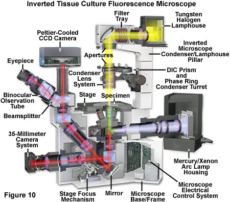
Figure 10 shows a schematic cross-section of a modern inverted (tissue culture) fluorescence microscope equipped with a Peltier cooled CCD image sensor and a traditional 35mm film camera system. Although filmcameraThe use of inverted microscopes is limited, but most still include ports for these accessories in the lower part of the front base. The microscope shown in Figure 10 can use a tungsten halogen lightbox mounted on a pillar to perform traditional bright field transmission illumination (with or without contrast enhancement). Mercury or xenon arc discharge lamps are used for fluorescence microscopes, with a reflective light illuminating device connected to a specially configured rear port. Aperture and field stop, as well as neutral density filter, enter near the port at the back of the microscope. In some inverted microscope models (not shown), an L-shaped reflective light illuminating device containing a diaphragm can be used to improve access to the rear auxiliary port for attaching accessories. In Figure 10, the light path through the microscope is represented by yellow for transmitted light, purple for unfiltered arc lamp illumination, green for filtered fluorescence excitation, and red for fluorescence emission.
Modern inverted microscope frames, like their upright counterparts, are composite materials designed and manufactured by computers for structural and thermal stability purposes. In addition, the mechanical platform components and circuit structure design have short stroke distances and high rigidity to avoid pitch and yaw when manipulating the objective lens steering gear during conventional operations such as DIC prism insertion or adjustment of the objective lens correction ring. The advanced objective turntable stage can effectively eliminate focal drift during delayed and prolonged fluorescence observation. Other stage options not available with standard upright microscopes include sliding and 360 degree rotating stages, glass stage inserts, heating plates, culture dishes and plate supports, and carbon dioxide incubators.
Inverted microscopes with modular design can be easily configured for research in electrophysiology, in vitro fertilization, microscopy, high-resolution DIC, video enhanced observation, and various advanced fluorescence technologies. These instruments are also easily applicable to confocal and multiphoton microscopes. Electric accessories include blinds, filter wheels, rotating objective disc, fluorescent block disc, focusing driver, and condenser lens. When combined with advanced objectives such as high working distance, water immersion, UV excitation, and phase contrast, inverted microscopes are ideal instruments for fluorescence studies of living cells and tissues, all with high optical correction.
Conclusion
In fluorescence microscopy, the widespread variations in local fluorophore concentrations within the sample, coupled with differences in extinction coefficient and quantum yield from one fluorescent dye to another, significantly affect the emission signal generated for a given amount of excitation intensity. Considering that many samples contain only trace amounts of fluorescent material in any specific field of view, the average fluorescence emission level generated by these combined factors is 4 to 6 orders of magnitude lower than the excitation intensity. In addition, there are some more complex fluorescence techniques, such as in situ hybridization and resonance energy transfer (FRET), where the emission signal intensity can be 9 to 10 orders of magnitude smaller than the excited emission signal intensity. In order to compensate for these large differences between excitation intensity and emission intensity, modern fluorescence microscopes must be able to attenuate excitation illumination more than one billion times without interfering with the fluorescence signal.
One of the main features of fluorescence microscopy is the high specificity of fluorescent probes that absorb and emit light at characteristic wavelengths, enabling this technique to selectively detect objective species at very low concentrations in complex mixtures. In addition, the high sensitivity and spatial resolution of fluorescence enable precise localization and study of individual molecules at length scales below the optical resolution of microscopes. Local environmental factors also severely affect fluorescence emission, making this method an ideal probe for pH, viscosity, ion concentration, molecular distance and orientation, membrane potential, hydrophobicity, charge distribution, and diffusion coefficient fluctuations. The time resolution of fluorescence is limited to the lifetime of the excited fluorescent probe, which can be in the nanosecond range. Due to the fact that many biological processes occur in this time domain, decay kinetics can reveal dynamic information about cellular processes. Overall, these factors are crucial in the application of fluorescence microscopy in cell biology.
In the past decade, fluorescence microscopy has developed at an astonishing pace, while laser technology, solid-state detectors, interference film manufacturing, and computer-based image analysis have also rapidly advanced. The development of high numerical aperture water immersion objectives further contributes to the study of biological phenomena, enabling researchers to deeply explore living cells in their natural environment. As microscope manufacturers respond to the constantly changing demands of the research community, the development of advanced fluorescent instruments and accessories will undoubtedly continue, and their ultimate contribution to exploring the mysteries of nature may ultimately have profound significance.