-
E-mail
info@auniontech.com
-
Phone
15601689581
-
Address
3rd Floor, Building 6, No. 2007 Hongmei Road, Xuhui District, Shanghai
Shanghai Haoliang Optoelectronic Equipment Co., Ltd
Introduction to Machine Vision 3D Imaging Technology (Part 1)
Date: 2025-10-17Read: 1
Introduction to Machine Vision 3D Imaging Technology (Part 1)
Overview of 3D Imaging Technology
Three dimensional imaging adds depth information to traditional two-dimensional imaging, enabling it to perform higher precision positioning, recognition, and detection tasks. It is now widely used in consumer electronics, pharmaceuticals, and industrial fields.
According to the data acquisition method, it can be divided into two types: contact based and non-contact based. Contact type can be divided into two types based on whether the tested object is damaged or not: non-destructive and destructive. Non contact signals can be divided into transmission and reflection based on their usage. Reflective can be further divided into two categories: optical and non optical. Optical lighting can be divided into two types: active and passive, depending on whether an artificial light source is needed. Passive visual imaging relies solely on the light radiation information generated by the target scene received by the camera, which is measured by the grayscale values of two-dimensional image pixels.
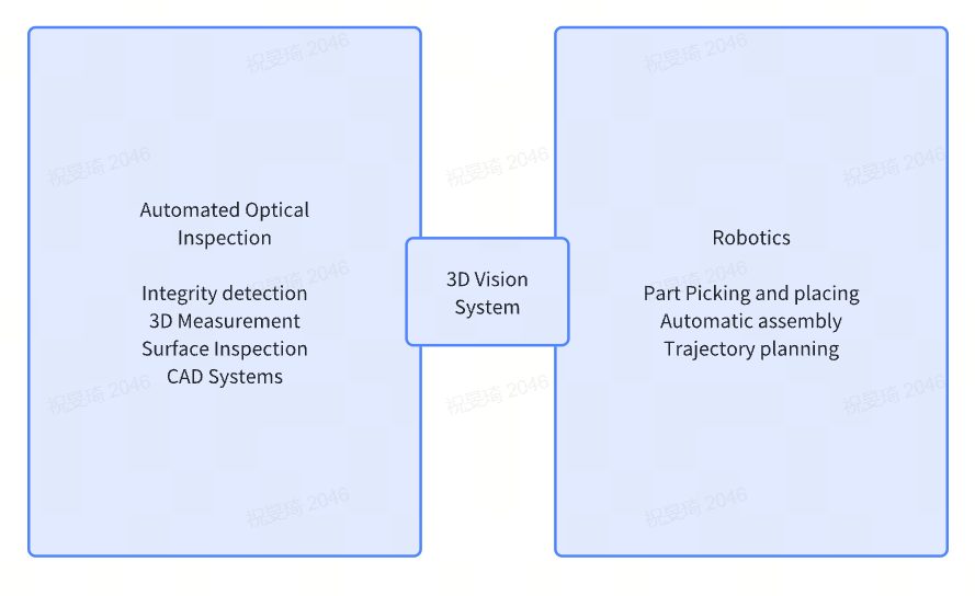
Passive vision is commonly used in three-dimensional imaging scenarios under specific conditions, such as indoors, target scenes with small radiation dynamic range and no occlusion, non smooth scene surfaces, and clear texture or geometric features, making it easy to find matching points through stereo matching. Active stereoscopic vision uses light modulation (such as encoded structured light, laser modulation, etc.) to illuminate the target scene, encode and mark the points on the surface of the target scene, and then decode the obtained scene images to reliably obtain matching points between the images, and then solve the three-dimensional information of the scene through triangulation. The advantages of active stereoscopic vision are strong anti-interference ability, low environmental requirements (such as eliminating environmental light interference through bandpass filtering), high 3D measurement accuracy, repeatability, and reliability. The disadvantage is that it is prone to occlusion problems in structurally complex scenes. According to the imaging principle, it can be further subdivided, as shown in the following figure:

Contact type is limited in size and prone to scratching the object being measured due to the need for probes or probes to move with the surface of the object being measured, resulting in poor accuracy. Coordinate Measuring Machine (CMM) measures the three-dimensional information of the object being measured through probes and discrete points on the surface of the object. At present, 3D imaging is mainly based on non-contact optical principles, which are safer, more efficient, and more accurate. An intuitive example is that in the past, road construction workers used metal rods similar to rulers to measure depth when repairing bumpy roads. There has never been an economical and efficient solution, but the application of 3D optical imaging technology has changed this process.
This article mainly discusses the mainstream 3D imaging technologies in the field of machine vision, including time-of-flight, structured light, laser triangulation, binocular stereo vision, and light field imaging technology. Finally, it will supplement the introduction of millimeter wave radar and laser radar, as well as the application scenarios and accuracy level comparisons of various 3D imaging schemes.
Flight time method
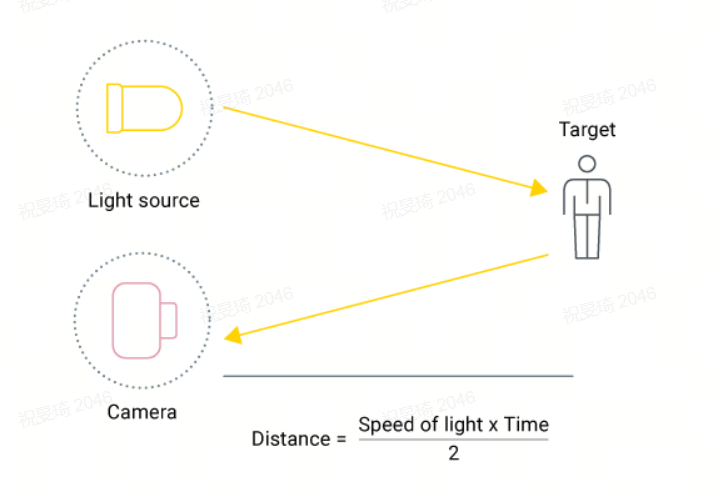
Time of Flight (ToF) measures the distance between the sensor and the object being measured based on the time difference between the emission and return of infrared light signals emitted by light emitting diodes (LEDs) or laser diodes (LDs). The ToF camera actively illuminates the object being measured by using a modulated light source (such as a laser), and then captures the reflected light using a sensor sensitive to the laser wavelength to measure the distance. The sensor measures the time delay ∆ t between the camera emitting light and the camera receiving the emitted light. The time delay is proportional to twice the distance (round-trip) between the camera and the object; Therefore, the distance can be estimated as depth=c Δ t/2, where c represents the speed of light. This process is similar to ultrasound, which measures distance through sound rather than light, while radar measures distance through radio waves. Compared to ultrasound, Time of Flight (ToF) cameras can generate high-resolution depth maps with high depth accuracy faster (with spatial resolution comparable to RGB cameras), and can cover a larger range - after all, the speed of light is much greater than the speed of sound. Although radar has a longer detection range, its accuracy and resolution in Time of Flight (ToF) are superior to those of traditional radar.
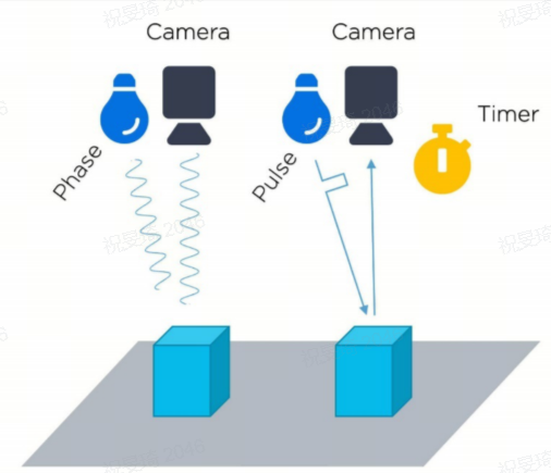
There are currently various methods for measuring ∆ T, among which two are the most commonly used: continuous wave (CW) method and pulse method. The continuous wave (CW) method, sometimes referred to as indirect time of flight (iToF), measures the phase shift between the transmitted and received light pulses. The pulse method, sometimes also known as direct time of flight (dToF), measures the time elapsed between the emitted pulse and the received light pulse. This method is similar to the principle of 3D laser sensors, except that 3D laser sensors scan point by point, while ToF cameras simultaneously obtain depth information of the entire image. It is worth noting that the vast majority of continuous wave ToF systems currently implemented and in use on the market use CMOS sensors, while pulse ToF systems use non CMOS sensors (especially CCD). One of the advantages of using CW iToF image sensors is that they are mass-produced based on traditional semiconductor infrastructure and can achieve high pixel density short-range imaging at an economical cost. Choosing iToF or dToF depth imaging system ultimately depends on application requirements and usage environment. IToF is suitable for short-range imaging that requires high spatial resolution (0.5 meters, 5 meters, and 10 meters). DToF is more suitable for long-distance imaging with low spatial resolution requirements. Artificial intelligence (AI) and optical system design make the boundary between choosing iToF technology and dToF technology less clear and distinct. In intelligent edge systems that can perceive the environment, both iToF and dToF sensors are integrated with RGB images and inertial sensors, and with the help of AI, their performance is improved to eliminate artifacts.
Just as the mouse has changed computer interaction and touchscreen technology has driven the popularity of smartphones and tablets, Time of Flight (ToF) technology is helping to achieve contactless 3D interaction. Time of Flight (ToF) technology has a similar effect in promoting the development of Industry 4.0. From industrial machine vision for quality inspection, to volume inspection for asset management, and to navigation technology for promoting autonomous (equipment) production, the manufacturing industry has begun to adopt these sensing technologies and gradually shift towards high-resolution systems suitable for harsh industrial environments. At present, there are numerous applications of Time of Flight (ToF) technology around us, ranging from car cockpit safety, to home sports equipment, to games and realistic 3D remote collaboration. Even for storage capacity testing in warehouses, barrels, and large storage tanks, it has a wide range of applications. One of the future applications of time of flight (ToF) technology is in autonomous vehicle as a supplement to radar, LIDAR and other depth sensors.
The current consumer grade ToF depth cameras mainly include Microsoft's Kinect 2, MESA's SR4000, and PMD Tech's ToF depth camera used in Google Project Tango. These products have been widely used in areas such as motion recognition, gesture recognition, and environmental modeling, with the most typical being Microsoft's Kinect 2.
ToF imaging can be used for 3D image acquisition with large field of view, long distance, low precision, and low cost. Its characteristics include fast detection speed, large field of view range, long working distance, and low price. However, its accuracy is low and it is susceptible to interference from ambient light. For smooth objects (reflecting light in different directions) or objects with angles (experiencing multiple reflections), the accuracy of time-of-flight imaging will be affected.
Similar to regular cameras, ToF camera chips require a lens at the front end to collect light. However, unlike ordinary optical lenses, a bandpass filter needs to be added here to ensure that only light with the same wavelength as the illuminating light source can enter.
Advantages of ToF: Due to the use of an active light source to illuminate the object being tested, it can still function normally even in the absence of ambient lighting. Compared with stereo cameras or triangulation systems, ToF cameras are compact in size and light in weight, almost the same size as regular cameras, making them very suitable for situations that require lightweight and small-sized cameras. The principle of time-of-flight algorithm is relatively simple, so ToF cameras can quickly calculate depth information in real time, reaching tens to 100fps. However, binocular stereo cameras require complex correlation algorithms and have slower processing speeds. The depth calculation of ToF is not affected by the surface grayscale and features of the object, and can perform 3D detection very accurately. However, binocular stereo cameras require the target to have good feature changes, otherwise depth calculation cannot be performed. Due to the extremely fast speed of light, ToF cameras require complex designs to detect the time difference between round-trip signals, making manufacturing relatively difficult. The depth calculation accuracy of ToF cameras does not change with distance, and can remain stable at the centimeter level throughout the entire measurement range. This is very meaningful for some large-scale motion applications. Compared to structured light cameras, ToF cameras have lower accuracy within a range of 10 meters and higher accuracy beyond 10 meters. A significant advantage of ToF cameras is their wide working distance, which can cover a range of 0.5 to 10 meters. In scenes with low accuracy requirements, some even reach several hundred meters. In this scenario, the illumination unit generally uses infrared LED instead of laser, which does not harm the eyes. The imaging range of structured light cameras is only 2 to 3 meters, but the accuracy will be higher. Therefore, although ToF cameras can work within a shorter range, they are not a good choice when a certain level of accuracy is required.
TOF depth cameras require high accuracy for time measurement, and the emitted pulses must be in a very short time (picosecond level). Even with the highest precision electronic components, it is difficult to achieve millimeter level accuracy. Therefore, in the field of close range measurement, especially within a range of 1 meter, the accuracy of TOF depth cameras still has a significant gap compared to other depth cameras, which limits its application in the high-precision field of close range. ToF cameras have certain advantages in long-distance distance measurement, but they are relatively expensive and do not have color information.
The accuracy of ToF cameras is largely related to distance, and it is generally believed that it can be estimated through an imaging distance of 1%. Therefore, if the object being measured is 5 meters away, ToF cameras can achieve an accuracy of 5cm. The accuracy of binocular stereo cameras is about 5-10% of the imaging distance, and structured light cameras have the highest accuracy, reaching 1mm.

Extension: Does optical radar belong to the time-of-flight type
Light Detection and Ranging (LiDAR), also known as Time of Flight Laser Scanner or sometimes referred to as Laser Radars, measures the distance of the object being measured by emitting laser pulses at multiple angles to the surrounding environment based on the time of flight. In addition, optical radar also measures the intensity of reflected light in order to reflect more details of the measured object on the depth map. In addition, 3D ToF can also be seen as a scanner free LiDAR technology.
SICKVisionary-T Mini3D camera
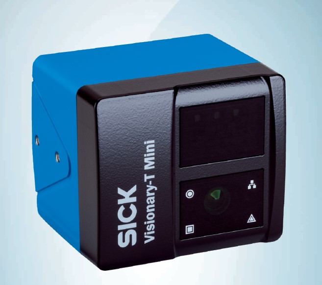
The SICK Visionary-T Mini 3D camera, with its 3D Time of Flight (TOF) technology, achieves compact housing and excellent data quality. The automation applications of robot technology, transport vehicles, and logistics rely on accurate and reliable 2D and 3D ranging data. In addition, even if the installation space is limited, the visual system should be easily integrated into the corresponding machine design. The SICK Visionary-T Mini 3D camera product line combines high performance with compact structural design and high cost-effectiveness. In addition, 3D vision sensors can provide detailed 2D and 3D scatter plots with high pixel density for data analysis. The automatic operation mode can simplify its machine integration and ensure easier operation.
About Haoai Intelligent
Haoai Intelligent is the professional agent of SICK in China's 3D vision field.
Haoai Intelligence focuses on providing comprehensive 3D machine vision solutions to help improve China's intelligent manufacturing level and industrial upgrading!
At present, we have a group of highly qualified 3D machine vision application engineers and algorithm development engineers, with complete machine vision project evaluation capabilities and underlying core algorithm development capabilities. Our 3D machine vision overall solution has been successfully implemented in multiple fields such as power batteries, automotive industry, consumer electronics, white goods, and rail transit inspection, accumulating rich experience in 3D machine vision project application and software development!
Haoai Intelligent's main products: 3D machine vision integrated solutions, including structured light 3D cameras, laser line scanning cameras, SICK 3D line laser contour sensors, TOF cameras, high-precision 3D measurement systems, visual guidance positioning systems, disordered grasping systems, etc. It can achieve functions such as flatness, height difference, positional measurement, concave convex defect detection, adhesive path detection, visual guidance robot polishing, visual guidance robot workpiece positioning and assembly, and workpiece disordered grasping.