-
E-mail
18083798558@163.com
-
Phone
18101455820
-
Address
No. 23 Haiwo Road, Guangling District, Yangzhou City
Jiangsu Ruyan Busbar Manufacturing Co., Ltd
What should be paid attention to in the design of molds for indoor and outdoor universal enclosed bus ducts?
Date: 2025-12-18Read: 36
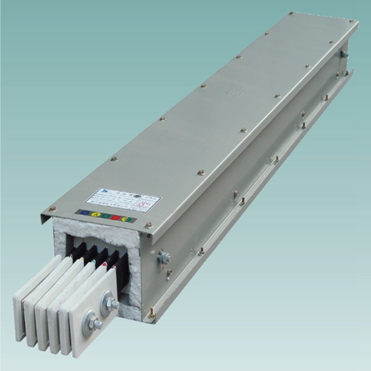
Indoor and outdoor universal enclosed bus ductIt refers to the industrial production of a transmission conductor formed by enclosing the busbar with a shell or cover within a certain length range. In the transmission system, enclosed busbars have been widely used, mainly in power plants, substations, industrial and mining enterprises, high-rise buildings and other places.
Indoor and outdoor universal enclosed bus ductDesign specifications and precautions:
1. Safety distance
The safety distance of enclosed busbars is a crucial parameter. Under normal circumstances, safety distance should consider factors such as usage environment, operating methods, working conditions, etc., and should specifically comply with national standards and industry norms. When the safe distance cannot be determined, compensation measures should be taken to ensure safe and reliable operation.
2. Ventilation and heat dissipation
Due to the narrow internal space of the enclosed busbar, heat cannot be effectively dissipated, therefore effective ventilation and heat dissipation measures must be taken. In the design process, appropriate heat dissipation methods should be selected based on the specific environment and workload, such as adding heat sinks, using forced air cooling, improving the surrounding environment, etc., to improve heat dissipation efficiency and ensure long-term normal operation of the equipment.
3. Grounding
The enclosed busbar must be reliably grounded to ensure personal safety and stable equipment operation. In design, attention should be paid to selecting appropriate grounding methods and materials to ensure that the grounding resistance meets the requirements, and timely inspection and maintenance should be carried out during use.
4. Drainage
There may be moisture inside the enclosed busbar, which can cause damage to the equipment. Therefore, effective drainage measures must be taken to drain the accumulated water outside the equipment. In the design, factors such as drainage location, drainage pipe diameter, and inclination angle should be considered to ensure smooth drainage and avoid moisture accumulation and humidity.
5. Maintenance and upkeep
In order to ensure the normal operation of the equipment, the enclosed busbar needs regular maintenance during use. Common maintenance includes checking grounding conditions, cleaning drainage pipes, inspecting radiators, checking conductor connections, etc. Only through proper maintenance and upkeep can equipment lifespan be extended and reliability improved.
6. The cross-sectional planning of the combined upper mold not only facilitates processing and heat treatment to ensure mold quality, but also facilitates the assembly and replacement of the upper mold.Reasonably select the clearance between the main mold, auxiliary mold, and the U-shaped groove of the lower mold body. The size of the gap is the main factor affecting the accuracy of the parts. The larger the gap, the worse the accuracy of the parts, but a gap that is too small can cause difficulty in demolding or scratches on the surface of the parts. Here, the size of the gap is determined through repeated experiments and mold modifications.To ensure that the height of the left and right shoulders of the main mold is consistent with the top surface of the U-shaped groove of the lower mold, the fillet size of the left and right shoulders directly affects the accuracy and quality of the workpiece. The larger the fillet or the uneven height of the left and right shoulders, the less ideal the edge pressing effect. If the fillet is too small, it will cause significant pressure marks on the surface of the workpiece. In the planning, we confirm that the rounded corner of the shoulder is R0 5.