-
E-mail
1173947150@qq.com
-
Phone
13588791425
-
Address
Room 1505, Building 10, China Merchants Shekou Canal Network Valley, Gongshu District, Hangzhou City
Hangzhou Langjie Measurement and Control Technology Development Co., Ltd
On site debugging guide for dynamic servo controller
Date: 2025-11-26Read: 0
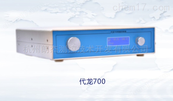
Dynamic servo controllerIt is the core control unit of industrial automation equipment, and its debugging quality directly determines the accuracy of motor operation and system stability. On site debugging should follow the principle of "safety first, gradual progress", forming a closed loop from hardware inspection, parameter configuration to functional verification, ensuring precise matching of the controller with the motor and load, and meeting the speed and position control requirements of the production line.
Pre debugging preparation: Build a solid foundation of security and hardware. Firstly, confirm that the power supply voltage of the controller matches the rated voltage of the motor (e.g. 220V servo motor corresponds to 220V controller input), and use a multimeter to test the insulation of the power line to avoid the risk of short circuit. Next, check the wiring between the motor and the controller - the encoder signal line should distinguish between phases A, B, and Z, the power line should ensure the correct sequence of phases U, V, and W, and the tightening torque of the wiring terminals should comply with the specifications (usually 0.8-1.2N · m) to prevent virtual connections from causing abnormal operation. Finally, connect the debugging software and establish a communication connection between the controller and the computer (Ethernet or RS485 communication is recommended).
Core parameter configuration: Implement controller and motor adaptation. The first step is to perform motor parameter self-tuning. In the "automatic tuning" mode of the controller, the system automatically identifies basic parameters such as motor model, rated speed, armature resistance, etc., and generates an adapted control model. If self-tuning fails, the motor nameplate parameters (such as rated current and power factor) need to be manually entered. The second step is to configure the control mode. The position control mode needs to set the electronic gear ratio (matching the motor encoder resolution and load pulse command), the speed control mode needs to set the source of the speed command (analog or communication) and the speed limit value, and the torque control mode needs to preset the maximum output torque to prevent overload.
Dynamic performance optimization: Improve operational accuracy and stability. By debugging software to monitor the motor operation curve, if there is startup jitter, it is necessary to increase the proportional gain of the position loop (P parameter) and reduce the integration time (I parameter); If overshoot occurs, the opposite is true. The optimization of the speed loop requires a focus on adjusting the proportional gain and differential gain (D parameter) to ensure a smooth transition of the motor from rest to rated speed, without speed fluctuations. For high-precision equipment such as CNC machines, the "feedforward control" function needs to be enabled to compensate for the impact of load inertia on position accuracy, so as to control the positioning error within ± 0.01mm.
Functional verification and safety testing: simulate actual working conditions for inspection. During the no-load testing phase, run the motor in position, speed, and torque modes respectively, check the consistency between the displayed speed and the actual speed (calibrated with a tachometer), and confirm that there is no lag in the forward and reverse switching. Load testing requires connecting to actual production loads, simulating maximum load conditions for 30 minutes, monitoring controller output current, motor temperature rise (normal ≤ 60K), and ensuring no overload alarms. The key focus of safety testing is to verify the emergency stop function - after triggering the emergency stop signal, the motor needs to stop within 100ms,Dynamic servo controllerCut off the output and lock it to prevent accidental startup.
Debugging completion: parameter saving and document recording. After all parameter configurations are completed, perform the "parameter save" operation (some controllers need to be powered off to save) to prevent parameter loss. Record debugging data, including motor models, controller parameter tables, screenshots of operating curves, and methods for handling exceptions, to form a debugging report. Finally, conduct on-site cleaning, organize wiring, and label line numbers to ensure easy maintenance in the future. Attention: If there is a controller alarm (such as overcurrent or overvoltage) during the debugging process, the machine should be stopped immediately for troubleshooting. Priority should be given to checking for issues such as load jamming and parameter setting errors to avoid forcefully running and damaging the equipment.